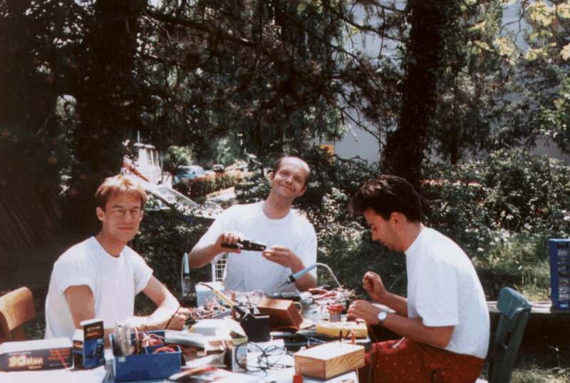
To make the fabrication of the Sync-Doubler easier, I have documented every step of the production of three Sync-Doublers Version 1.1 that two friends of mine, Patrick Kramper, Christian Hettich and myself have build during a sunny weekend in June 1998.
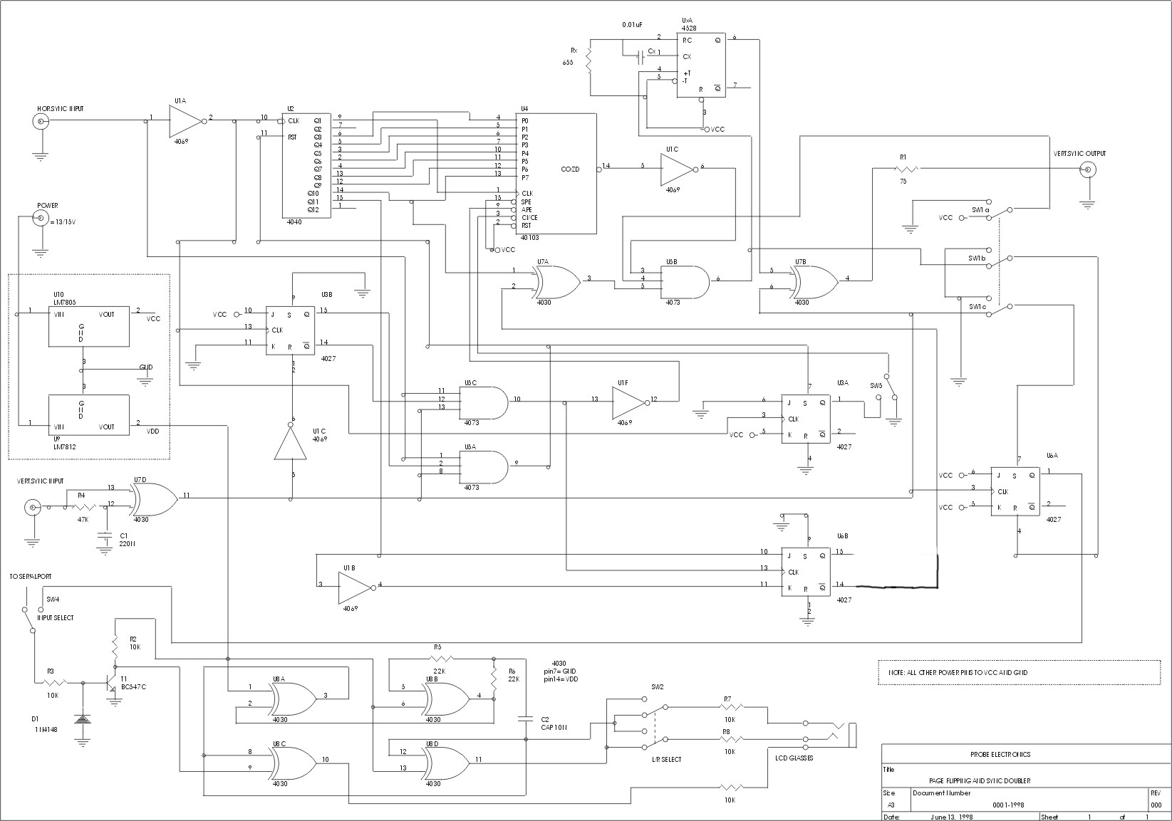
You will find a list of all the parts you need to fabricate the Sync-Doubler in the partlist. You also need to print out the following files: the plan, the complete layout in 300 dpi or the complete layout in 360 dpi, the Layout in 300 dpi or the Layout in 360 dpi depending on your printer, the wirering diagram, the timing diagram and the test circuit diagram. Stanley Fredriks improved the design of the circuit, to make it compatible to more types of computer monitors and draw a nice circuit diagram. This circuit diagram shows Version 1.2 of the Sync-Doubler but it can also be used to build Version 1.1. I'm sorry that I do not have a layout for Version 1.2 yet. If somebody likes to do this work, it would be welcome.
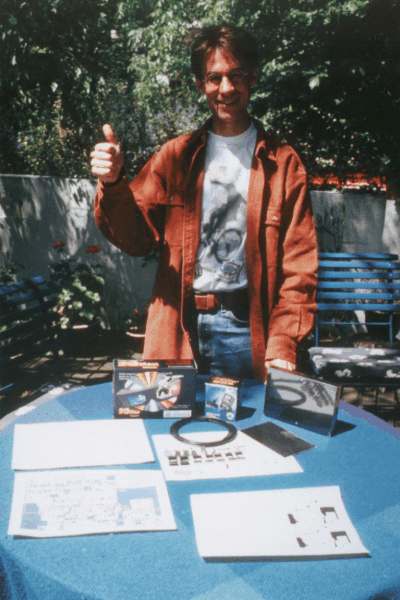
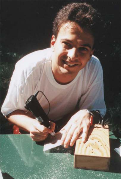
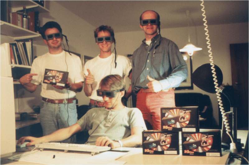
On the next picture you can see all the parts necessary to build the Sync-Doubler. You have to spend a maximum of 70 DM for the parts, 20 DM for the power supply and 38,80 DM for the LCD shutter glasses (The 3D Max Shutterglasses are availaible at PEARL) The guy behind the table, that's me.
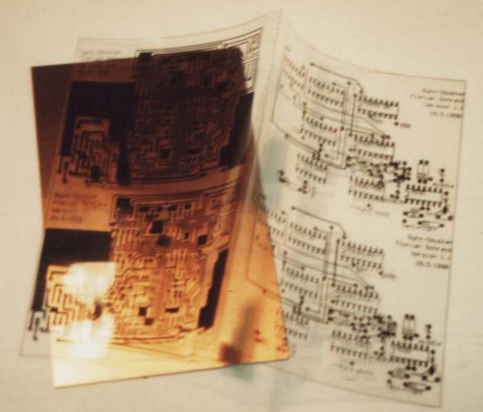
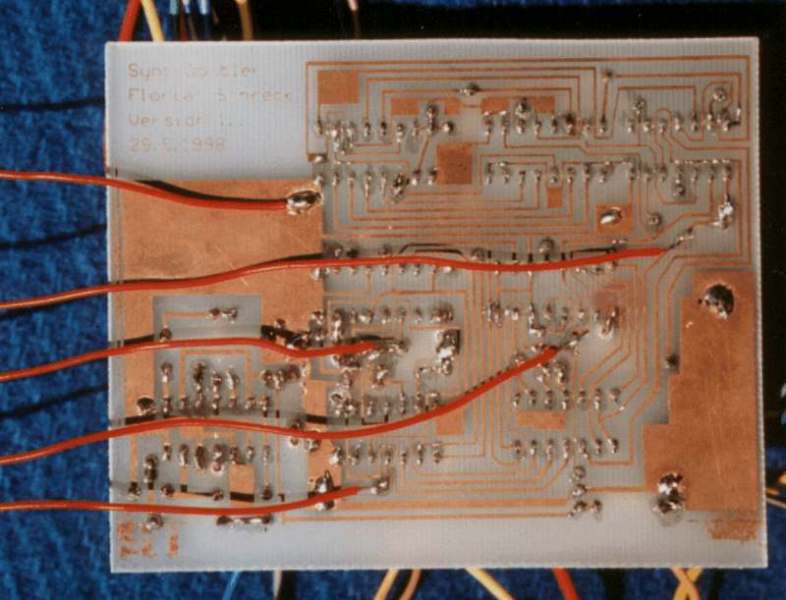
The board can be bought from Jens Heck , or you can fabricate it yourself. First copy the Layout to a transparancy. Black should be really black, if it isn't, use a Edding to improve it. Fold the transparency along the dotted line. and attach it to both sides of the board using scotch. Pay attention that the text is readable on both sides and that you do not interchange the components side with the soldering side. You should use a single layer board.
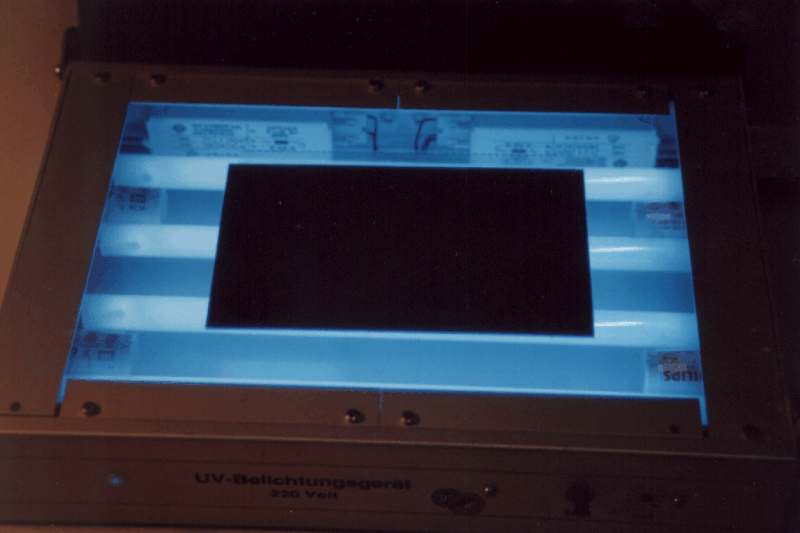
Now put BOTH SIDES of the board in UV radiation. Doing so, you will see the position of the components marked on the component side after development. You can also use the sun as source of UV radiation.
Now You have to develop the board. The necessary chemicals are cheap and available in every electronics shop.
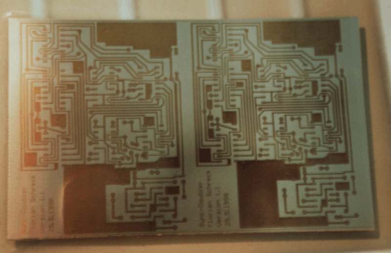
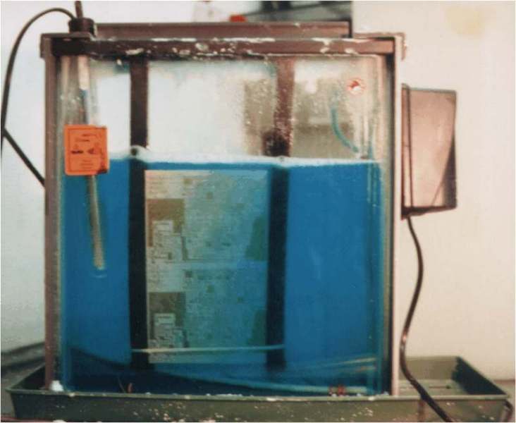
The next step is to remove the unnecessary copper. You can use Fe-III-Cl for this. You do not need a professional machine like the one on the picture. It will only take a longer time if you dont't have such a thing.
Now you put the soldering side again in UV radiation and develop the board once again to remove the unnecessary protection coating.
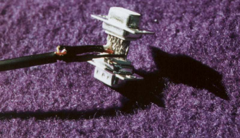
Now comes the fabrication of the VGA-paththrough connector. Take 14 wires, about 1cm long each (the wire can be taken from resistors for example). Sold them to the male VGA connector, leaving out pin 14. Bend down the wires from pin 11 to pin 15, so that you can easily sold the female VGA connector on top of the construction. Bend the wires up again and sold them.

Often the wires in shielded cables are very weak. To get a more stable connector, first sold short (2cm) thick (0,75qmm) wires to the wires in the cable, protect them with shrink tubing and sold these wires to the VGA paththrough connector. Do so on both sides of the cable.
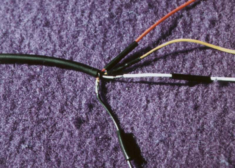
Connect the three wires of the cable to pin 13, pin 14 male and pin 14 female. Connect the shielding to GND pin 6.
First drill the holes into the board. A 0,75mm drill works fine.
Now put all the parts in their places and sold them.
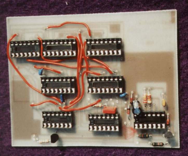
Doing this work in a nice garden with friends can be a lot of fun.
Sold all the switches to the board according to the wirering instructions.
Switch 3, on/off: if the sync-doubler is switched of, the v-sync signal is directely passed through. Pay special attention when soldering this switch. Do not give the 12V voltage supply any chance to ever get in contact with the v-sync signals. This could damage your monitor or computer. It's an good idea to shield the 12V cables witch scotch.
Switch 5, number of h-syncs between two v-syncs is multiple of four or multiple of four plus two. If you are only playing H3D games on a Voodoo card, you can leave out this switch and directely connect S5B to S5M.
Switch 1, sync-doubling, page flipping: besides sync-doubling there are other methods of displaying stereoscopic images. See Christoph Bungerts page for a detailed description. With page flipping you can play older games like Descent II. If you are only playing H3D games on a Voodoo card, you can leave out this switch and directely connect S1B(x,y,z) to S1M(x,y,z).
Switch 4, l/r, r/l: toggles left and right glasses. Can be left out if only sync-doubling is used.
Plug external: You can connect the controller to the serial, parallel or vesa 3 port to get compatibility to Nuvfrag, Cyberboy etc. If you are only playing H3D games on a Voodoo card, you can leave out this plug and directly connect l/r to left/right on the sync-doubler board.
Before connecting the circuit to the power supply, make sure that there is no short circuit between GND and +5V. Connect the power supply. Check that every chip has +5V and GND and that the LED is on. Switch everything off and insert the chips. Use the LCD-shutter glasses and the left/right toggle switch to check the LCD-Driver circuit. Test the circuit using this testing circuit, which emulates the graphic card and the monitor.
Sold wires to +5V, GND, h-sync in, v-sync out and to pin 5 of the 4069. Connect the test circuit to these cables. Connect "v-sync inp" from the test circuit to pin 5 of the 4069 and bend up pin 11 of the 4030 which contains XOR 3. Do not forget to bend pin 11 down again, when using the circuit with a computer.
The whole test-circuit looks like this.
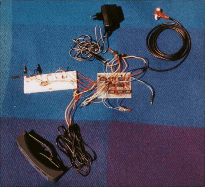
Use the switches to simulate the timing diagram. With the LED logic indicator you can check one signal after the other. Normaly the error is found fast using this method.
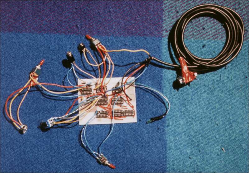
Remove the test cables and put your Sync-Doubler into a box.
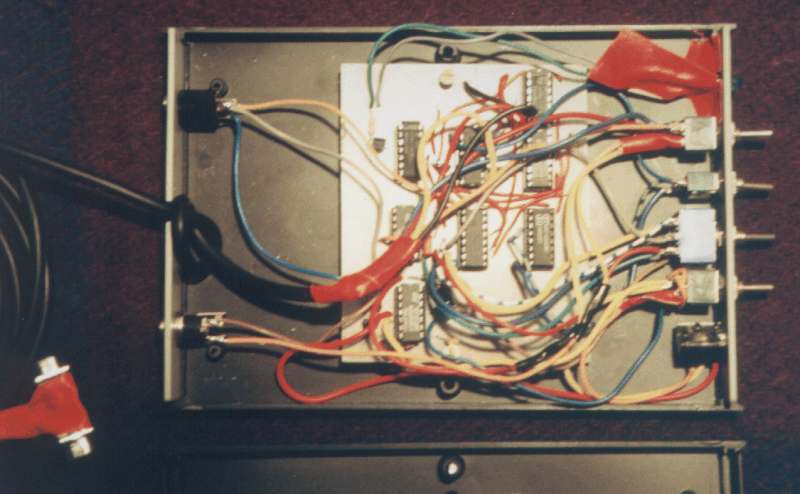
Finally your Sync-Doubler should look somewhat like this.
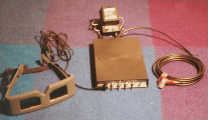
Now comes the most important step. Download the drivers for Quake II from H3D(TM), install them and play H3D Quake. You should see two pictures divided by a black bar. Connect the Sync-Doubler between your Voodoo Card and the Monitor. Switch it on and select Sync-Doubling. Put the #4n/#4n+2 Switch in the #4n+2 position. Now the Monitor should show the two pictures one after the other. Use the left/right switch to get the correct 3D effect. You can adapt the effect to your eyes and monitorsize using special commands for Quake II. (See H3D) If the circuit Version 1.1 does not work with your monitor, you have to modifie it according to Stanley Fredriks improved Layout Version 1.2 circuit diagram. He tested this with 20 Monitors and all worked.
Have a lot of fun with your new Sync-Doubler.
Back to the Sync-Doubler main page.
Last modified: 20.6.1998